2. Universal Payload
July 30, 2024
A new Universal Payload specification is published at https://universalpayload.github.io/spec/. USF Universal Payload is going to adopt this new Universal Payload specification.
February 1, 2023
2.1. Purpose
The purpose of this document is to describe the architecture and interfaces between the bootloader and the payload. Bootloader or payload implementation specific details are outside the scope of this document.
2.2. Intended Audience
This document is targeted at all platform and system developers who need the bootloader or payload to support the unified bootloader and payload interface. This includes firmware developers, bootloader developers, system integrators, and end users.
2.4. Universal Payload Overview
Most modern platforms rely on system firmware to initialize the hardware and launch an Operating System (OS). The system firmware is responsible for initializing the platform hardware including CPU and other silicon functional blocks, detecting and initializing the memory subsystem, boot media initialization and setting up hardware abstractions for use by the operating systems.
While newer architectural enhancements such as PCI, PCIe, and USB are developed at an industrial scale, there are vendor specific micro-architectural enhancements that happens at a much faster pace. Silicon vendors differentiate through these microarchitectural enhancements and these features are often considered intellectual property and rely on system specific firmware initialization. The system firmware thus provides the necessary abstraction and allows a generic operating system to run on different platform configurations and technologies without needing any changes to the operating system itself.
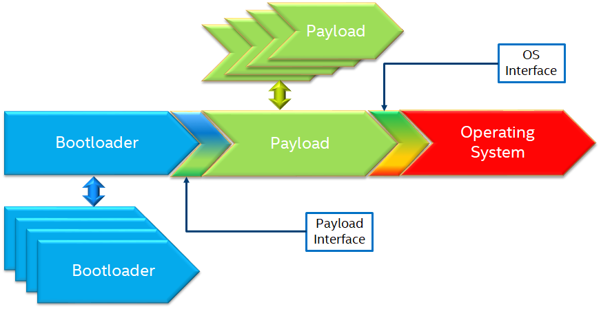
A design methodology of viewing system firmware functionality as made up of two distinct phases (initialization and OS boot logic) is gaining traction resulting in newer implementations of system firmware. This approach calls for modular phases with an initialization phase (bootloader) which completes the system initialization and gets the hardware to a usable state and then a payload phase. The payload can provide/implement many different functionalities including media and file system drivers, operating system boot, diagnostics, etc.
While certain system firmware implementations implement both the initialization and OS boot logic in a single code base, the distinction lies in the functionality provided.
This specification describes an interface between the bootloader phase that initializes the system hardware and the payload phase. It includes how to pass parameters to the payload and parameter format, payload image format, payload boot mode and stack usage, etc. The intent for this specification is to provide interoperability between spec compliant bootloaders and spec compliant payloads.
2.5. Bootloaders
Bootloaders are primarily responsible for initializing the system hardware including, but not limited to CPU initialization, memory detection and initialization, initialization of silicon functional units (IO controllers), bus topology configuration, etc. In addition to the initialization itself, bootloader is responsible for providing the system configuration information to the subsequent stages in the boot process. In addition to proprietary options, there are many open sourced bootloaders available.
EDK II
TianoCore EDK II is a modern feature-rich, cross-platform firmware development environment for the UEFI and UEFI Platform Initialization (PI) specifications. EDKII performs both first stage (hardware initialization) and second stage booting.
Reference implementations for many platforms are also available in open source, under BSD + Patents license.
Slim Bootloader
Slim Bootloader is an open source system firmware implementation that adopts the modular initialization followed by payload launch approach of system firmware design. Slim Bootloader provides both the initialization phase and OsLoader payload, and it also supports launching of different payloads. Open source Slim Bootloader uses a BSD + Patents License.
https://slimbootloader.github.io/
coreboot
Coreboot is a project to develop open source boot firmware for various architectures. It follows the design philosophy of minimum necessary initialization followed by payload. Coreboot is released under GNU’s General Public License (GPL).
U-Boot
U-Boot is an open-source, primary bootloader used in embedded devices. U-Boot performs both first stage (hardware initialization) and second stage booting. U-boot is released under GNU’s General Public License (GPL)
2.6. Payload Modules
After initializing the system hardware, bootloaders launch the payload modules. Payloads ideally are modular and platform independent. Payloads depend on abstract interfaces (scope of this document) to be platform independent.
While OS boot protocol is one of the main functionalities provided by payloads, there could be other functionalities such as diagnostics that can be enabled by payloads.
From a design point of view, a payload is different from a boot image based on its relationship with the system firmware. Payloads are considered part of system firmware and are typically in flash memory, while boot images are not considered part of system firmware (not within the trusted firmware boundary) and are often in separate boot media.
As mentioned earlier, while certain system firmware implementations include both the initialization and OS boot logic in a single code base, the distinction lies in the functionality provided. This leads to use cases where some system firmware implementations can act as a payload providing OS boot capability, while relying on an underlying bootloader layer for system hardware initialization. Examples of such payloads include TianoCore EDKII and U-boot. Both EDKII and uboot implementations include both phases of system firmware functionality, and can also be launched as payloads by other bootloaders.
There are many payloads currently available, including the EDKII UEFI payload, Linux payload, u-boot payload and other custom payload implementations.
EDK II Payload
EDK II DXE and BDS stages can be launched by bootloaders as a UEFI payload. The EDK II payload provides the required UEFI specification defined architectural protocols, and can launch a UEFI aware OS.
SBL OsLoader
This is an SBL payload implementation that supports the Linux boot protocol, and can also launch ELF or PE executables. It also supports launching an OS compliant with the Multi-Boot specification.
Linux Payload
LinuxBoot is firmware for modern servers that replaces specific firmware functionality, like the UEFI DXE phase with a Linux kernel and runtime.
VaultBoot Payload VaultBoot is a firmware security payload highly focus on trusted computing and advanced defense, e.g: Verified boot (also known as Secure Boot) and measured boot, TPMv2 based FDE (Full-disk encryption), local/remote attestation, built-in DH key exchange against physical attack such as TPM Genie.
2.7. Bootloader Interfaces
2.7.1. Coreboot Payload Interface
Reference: https://www.coreboot.org/API
Reference: https://doc.coreboot.org/lib/abi-data-consumption.html
Reference: https://github.com/tianocore/edk2/blob/master/UefiPayloadPkg/Library/CbParseLib/CbParseLib.c
Coreboot passes information to downstream users (payloads and/or operating systems) using coreboot tables.
The table usually sits in memory around address 0x500. However, some bootloaders seem to overwrite low memory area, thus destroying the coreboot table integrity, rendering the table useless. So, the coreboot tables were moved to the high tables area.
When coreboot tables were moved to high memory, a 40 bytes mini coreboot table with a single sub table is placed at 0x500/0x530 that points to the real coreboot table. This is comparable to the ACPI RSDT or the MP floating table.
Coreboot tables contain a series of data records packed back to back, with each encoding both type and size. This is something similar to a UEFI HOB list. Coreboot tables provide information about:
memory map
Graphics Info
Pointers to certain CBMEM structures, such as ACPI, SMBIOS, etc.
2.7.2. Slim Bootloader (SBL) Payload Interface
Reference: https://slimbootloader.github.io/developer-guides/payload.html
Reference: https://uefi.org/sites/default/files/resources/PI_Spec_1_7_final_Jan_2019.pdf
Reference: https://github.com/tianocore/edk2/blob/master/UefiPayloadPkg/Library/SblParseLib/SblParseLib.c
SBL supports ‘loosely coupled payload’, which basically refers to payloads built independently (no source sharing). SBL builds a series of data structures called the Hand Off Blocks (HOBs) and provides a pointer to this HOB List to the payloads. These data structures conform to the HOB format as described in the Platform Initialization (PI) Specification.
2.7.3. PEI to DXE Interface
Reference: https://uefi.org/sites/default/files/resources/PI_Spec_1_7_final_Jan_2019.pdf
PEI must also provide a mechanism for components of DXE and the DXE Foundation to discover the state of the system when the DXE Foundation is invoked. Some aspects of the system state at handoff are architectural; others may vary and those must be described to DXE components.
The DXE IPL PPI passes the Hand-Off Block (HOB) list from PEI to the DXE Foundation when it invokes the DXE Foundation. The handoff state is described in the form of HOBs in the HOB list.
Required HOB Type |
Usage |
|---|---|
Phase Handoff Information Table (PHIT) HOB |
This HOB is required. |
One or more Resource Descriptor HOB(s) describing physical system memory |
The DXE Foundation will use this physical system memory for DXE. |
Boot-strap processor (BSP) Stack HOB |
The DXE Foundation needs to know the current stack location so that it can move it if necessary, based upon its desired memory address map. This HOB will be of type EfiConventionalMemory |
One or more Resource Descriptor HOB(s) describing firmware devices |
The DXE Foundation will place this into the GCD. |
One or more Firmware Volume HOB(s) |
The DXE Foundation needs this information to begin loading other drivers in the platform. |
A Memory Allocation Module HOB |
This HOB tells the DXE Foundation where it is when allocating memory into the initial system address map. |
2.8. OS interfaces
While this specification aims to document the bootloader to payload interface, the payload to OS interface is briefly discussed just for the sake of completeness.
2.8.1. OS Boot protocols
UEFI
UEFI stands for “Unified Extensible Firmware Interface.” The UEFI Specification defines a new model for the interface between personal-computer operating systems and platform firmware. The interface consists of data tables that contain platform-related information, plus boot and runtime service calls that are available to the operating system and its loader. Together, these provide a standard environment for booting an operating system and running pre-boot applications.
https://uefi.org/specifications
Linux Boot Protocol
Linux kernel can itself be a bootable image without needing a separate OS Loader. The Linux boot protocol defines the requirements required to launch Linux kernel as a boot target.
https://www.kernel.org/doc/html/latest/x86/boot.html
Multiboot Protocol
The Multiboot specification is an open standard describing how a boot loader can load an x86 operating system kernel. The specification allows any compliant bootloader implementation to boot any compliant operating-system kernel. Thus, it allows different operating systems and bootloaders to work together and interoperate, without the need for operating system specific bootloaders.
https://www.gnu.org/software/grub/manual/multiboot2/multiboot.html
2.8.2. Data interface
Modern computer buses and devices such as PCI, PCIe, USB, and SATA support software detection, enumeration and configuration, providing true plug and play capabilities. However, there still exist some devices that are not enumerable through software.
Examples:
PCI Host Bridge
GPIO
Serial interfaces like I2C, HS-UART, etc.
Graphics framebuffer
Device Management information including manufacturer name, etc.
While it is possible to write platform specific device drivers to support such devices/interfaces, it is efficient for the platform specific firmware to provide information to the platform independent operating system.
There are two data protocols that are used extensively for this purpose: ACPI and devicetree.
ACPI
Advanced Configuration and Power Interface (ACPI) provides an open standard that operating systems can use to discover and configure computer hardware components and to perform power management and status monitoring. In October 2013, ACPI Special Interest Group (ACPI SIG), the original developers of the ACPI standard, agreed to transfer all assets to the UEFI Forum, in which all future development will take place.
SMBIOS
System Management BIOS (SMBIOS) is the premier standard for delivering management information via system firmware.
https://uefi.org/specifications
https://www.dmtf.org/standards/smbios
Devicetree
The devicetree is a data structure for describing hardware. A devicetree is a tree data structure with nodes that describe the devices in a system. Each node has property/value pairs that describe the characteristics of the device being represented.
2.9. Payload principle
Keep interface as clean and simple as possible.The payload should encapsulate the boot abstractions for a given technology, such as UEFI payload or LinuxBoot. The Payload should vie to be portable to different platform implementations (PI), such as coreboot, Slim bootloader, or an EDKII style firmware.The payload should elide strong dependencies on the payload launching code (e.g., coreboot versus EDKII versus Slim Bootloader) and also avoid board-specific dependencies. The payload behavior should be parameterized by the data input block.Open: Should Payload return back to bootloader if payload fail?Answer: No for first generation. No callbacks into payload launcher.Open: Do we need callback from payload to bootloader? Avoid it if possible
Open: How to support SMM for booloader and Payload? Where is trust boundary.Answer: SMM should be either part of the payload for present generation Management Mode (MM) PI drivers, but longer term the EDKII PI independent MM modules should be used. The latter are a class of SMM drivers (or TrustZone drivers for ARM) that are not launched via DXE. For coreboot SMM can be loaded from ramstage, the PI payload launcher, or elided from ramstage and use the portable MM handlers.If there is an existing standard it will be used (e.g., ACPI table that is simple to parse).
2.10. Payload Security
Payload is part of system firmware TCB
Today the payload is provisioned as part of the platform initialization code. As such, the payload is protected and updated by the platform manufacturer (PM). The payload should be covered by a digital signature generated by the PM. The platform owner (PO) should not be able to update the payload independently of the PM.
The platform initialization (PI) code should be the platform root of trust for update, measurement, and verification. As such, the PI code that launches the payload should verify the payload using payload Hash or using a key to verify its signature. The PI code should also provide a measurement into a Trusted Platform Module (TPM) of the payload into a TPM Platform Configuration Register (e.g., PCR[0]). The payload may continue the measured boot actions by recording code executed in the payload phase into PCRs (e.g., UEFI driver into PCR[2], UEFI OS loader into PCR[4]).Open: Do we need a capability boot to say if payload supports/requires measured/verified boot?
2.11. Payload Image Format
Payload, as a standalone component, usually needs to be loaded by a bootloader into memory properly prior to execution. In this loading process, additional process might be required, such as assembling, rebasing, authenticating, etc. Today, many payloads use their own image formats (PE, ELF, FV, RAW, etc.), and it is very challenging for a bootloader to identify and support all of them.
To address this, a common payload image format is desired to facilitate the payload loading process. Instead of defining a new image format for payloads, it is preferred to reuse an already-existing format, such as ELF (Executable and Linkable Format) and PE (Portable Executable). This specification selects the ELF image format as the common universal payload image format, since it is flexible, extensible, and cross-platform. It is also adopted by many different operating systems on many different hardware platforms.
For detailed information on the ELF image format, please see ELF Specification .
2.11.1. Payload Image Sections
To use ELF image as universal payload image format, it is required to define a simple way for bootloader to differentiate a universal payload image from a regular ELF image. On the other side, a universal payload might also need additional image information to proceed with the boot flow. This specification requires the universal payload image to provide these additional required information through new defined ELF sections, Universal Payload Information Section, and Universal Payload Loaded Image Section.
2.11.2. Universal Payload Information Section
This specification requires a mandatory ELF universal payload information section to indicate the ELF image conforms to this specification. If this section is found inside the ELF image and is valid, the bootloader can retrieve universal payload specific information from this section, such as payload version, payload ID, etc. And the bootloader shall use the interfaces defined in this specification to handoff the control to the payload.
This Universal Payload Information section must:
Have section name defined as “.upld_info”
Have section aligned at 4-byte boundary within the ELF image.
Contain UNIVERSAL_PAYLOAD_INFO structure in its section, as defined as below:
UNIVERSAL_PAYLOAD_INFO Structure
Byte Offset |
Size in Bytes |
Field |
Description |
|---|---|---|---|
0 |
4 |
Identifier |
‘PLDH’ Identifier for the unverial payload info. |
4 |
4 |
HeaderLength |
Length of the structure in bytes. |
8 |
2 |
SpecRevision |
Indicates compliance with a revision of this specification in the BCD format. 7 : 0 - Minor Version 15 : 8 - Major Version For revision v0.90, the value will be 0x0090. |
10 |
2 |
Reserved |
Reserved for future use. |
12 |
4 |
Revision |
Revision of the Payload binary. Major.Minor .Revision.Build The ImageRevision can be decoded as follows: 7 : 0 - Build Number 15 :8 - Revision 23 :16 - Minor Version 31 :24 - Major Version |
16 |
4 |
Attribute |
Bit-field attribute indicator of the payload image. BIT 0: Build Type. 0: Release Build 1: Debug Build |
20 |
4 |
Capability |
Bit-field capability indicator that the payload image can support. BIT 0: Support SMM rebase |
24 |
16 |
ProducerId |
A null-terminated OEM-supplied string that identifies the payload producer. |
40 |
16 |
ImageId |
A null-terminated ASCII string that identifies the payload name. |
2.11.3. Universal Payload Loaded Image Section
There are many cases that a payload might need extra images to proceed the boot flow. For example, UEFI payload might need additional FV images, Linux payload might need additional InitRd image, u-boot might need additional devicetree blob, etc. In these cases, it is desired to pass this additional image information from bootloader to payload so that payload can consume these images later.
This specification defines optional universal payload extra image sections. If they exist, they hold extra image information to be passed into the universal payload. Please note, multiple extra image sections might exist in single universal payload ELF image.
If a universal payload extra image section needs to be provided, it must:
Have unique section name defined as “.upld.*”. The full section name string length needs to be less than 16. Here, ‘*’ can be any ASCII string.
Have section aligned at proper boundary within the ELF file as required by the nature of the extra image itself. For example, FV and InitRd might need 4KB page-aligned.
Contain the raw extra image data in its section.
During payload image loading, the bootloader shall build these extra images into HOB. And the universal payload can locate the information from the HOB and find required extra image information for consumption.
2.12. Hand-off state
The bootloader builds the Hand-Off Block (HOB) list containing platform specific information and passes the address of the HOB list to the payload.
The prototype of payload entry point is defined as:
typedef
VOID
(*PAYLOAD_ENTRY) (
  EFI_HOB_HANDOFF_INFO_TABLE *HobList
);
The compiler need use a proper attributes for this function to meet the calling convention below. For example, Microsoft Visual studio uses __cdecl for X64, while Linux GCC uses __attribute__((ms_abi)) for X64.
HOB List defines the detailed HOB list being used to transfer platform specific data from the bootloader to the payload.
2.12.1. IA-32 and x64 Platforms
2.12.1.1. State of silicon
The bootloader initializes the processor and chipset through vendor-specific silicon initialization implementation. For example, FSP is a binary form of Intel silicon initialization implementation. Typically, when the control transfers to the payload:
The memory controller is initialized such that physical memory is available to use.
Processors (including application processors) are patched with microcode and initialized properly.
The PCI bus is assigned with proper bus numbers, IO/MMIO space.
The Graphics controller may be initialized properly.
But the bootloader could do less silicon initialization if the responsibilities of the payload and the bootloader are well defined (out of the scope of this document).
2.12.1.2. Instruction execution environment
Regardless of the environment where the bootloader runs, the processor is in 32-bit protected mode when a 32-bit payload starts, or in 64-bit long-mode when a 64-bit payload starts. The payload header contains the machine type information that the payload supports.
The following sections provide a detailed description of the execution environment when the payload starts.
2.12.1.2.1. Registers
ESP + 4 points to the address of the HOB list for the 32-bit payload.
RCX holds the address of the HOB list for the 64-bit payload.
Direction flag in EFLAGs is clear so the string instructions process from low addresses to high addresses.
All other general-purpose register states are undefined.
Floating-point control word is initialized to 0x027F (all exceptions masked, double-precision, round-to-nearest).
- Multimedia-extensions control word (if supported) is initialized to 0x1F80 (all exceptionsmasked, round-to-nearest, flush to zero for masked underflow).
CR0.EM is clear.
CR0.TS is clear.
2.12.1.2.2. Interrupt
Interrupt is disabled. The hardware is initialized by the bootloader such that no interrupt triggers even when the payload sets the Interrupt Enable flag in EFLAGs.
2.12.1.2.3. Page table
Selectors are set to be flat.
Paging mode may be enabled for the 32-bit payload. (have general term on how it could be enabled if enabling page mode).
Paging mode is enabled for the 64-bit payload.
When paging is enabled, all memory space is identity mapped (virtual address equals physical address). The four-level page table is set up. The payload can choose to set up the five-level page table as needed.
2.12.1.2.4. Stack
4KiB stack is available for the payload. The stack is 16-byte aligned and may be marked as non-executable in page table.
discussion: Should payload declare its required stack size in the payload header?
Payload could setup its own stack, there is no restriction to setup a new stack.
2.12.1.2.5. Application processors
Payload starts on the bootstrap processor. All application processors (on a multiple-processor system) are in halt state.
Use mWait and mBox to wake up. (Follow ACPI table). How about the legacy bootloader? Assume something if ACPI is not there.
TODO: take care about virtual platforms.
2.12.2. ARM Platforms
Need community inputs
2.12.3. RISC-V Platforms
Need community inputs
2.13. Payload Interfaces
The bootloader provides platform information to payload through standard ACPI table, SMBIOS table, Devicetree and a series of data structures called the Hand Off Blocks (HOBs). If the information is already defined in the ACPI specification, SMBIOS specification or devicetree, the payload could parse them to get the required information. For the platform information that is not defined in the standard tables, the bootloader should build a HOB list to pass it to the payload.
Open: Do we need a set of configuration data to config payload?
We do not believe so.
Open: Do we need pass data from payload to bootloader to impact bootloader behavior in next boot?
Keep it open now.
Open: will payload be run in S3 path?
Suggest skipping payload.
2.13.1. ACPI tables
ACPI table is required to boot modern operation system, especially to boot windows operating system. The bootloader should provide an ACPI RSDP HOB. In the ACPI table least RSDT, FADT and MCFG should be available to the payload.Payload could remove/add/modify the ACPI table passed from the bootloader if required.
The payload could parse the ACPI table to get some basic platform information. For example, the Fixed ACPI Description Table (FADT) defines various fixed hardware ACPI information to an ACPI compatible OS, such as the base address for the following hardware registers blocks: PM1a_CNT_BLK, PM_TMR_BLK, PM1a_EVT_BLK, GPE0_BLK, PM1b_EVT_BLK, PM1b_CNT_BLK, PM2_CNT_BLK, and GPE1_BLK. The payload could use them and other values (e.g. RESET_REG, RESET_VALUE) to make the payload platform independent.
The other example is to get the PCIE base address from ACPI memory mapped configuration space access table definition, defined in the PCI Firmware Specification. http://www.pcisig.com <http://www.pcisig.com/>.
And another example is on the debug device info. The bootloader might report debug device following up ACPI Debug Port Table 2 (DBG2). If a fully 16550-compatible serial device is specified in the ACPI DBG2, bootloader should provide a Serial Debug Information HOB in the HOB list so that the payload could use same debug device with same setting. If the ACPI DBG2 table could not be found, the payload should use serial device provided by the Serial Debug Information HOB as the default debug device.
2.13.2. HOB List
The bootloader should build a HOB list and pass the HOB list header to payload when passing control to payload. The HOB format is described in the Platform Initialization (PI) Specification - Volume 3: Shared Architectural Elements.
There are two sections below describing the HOBs produced by the bootloader and consumed by the payload for providing the system architecturally information.
First section describes the HOBs defined in Platform Initialization Specification Volume 3: Shared Architectural elements.
Second section defines the new HOBs.
2.13.2.1. Reusing Interfaces in Platform Initialization Specification
2.13.2.1.1. PHIT(Phase Handoff Info Table) HOB
The bootloader should report the general state information through the HOB following EFI_HOB_HANDOFF_INFO_TABLE format defined in Platform Initialization Specification Volume 3: Shared Architectural elements.
2.13.2.1.2. CPU HOB
The bootloader should report the processor information including address space and I/O space capabilities to the payload through the HOB following EFI_HOB_CPU format defined in Platform Initialization Specification Volume 3: Shared Architectural elements.
2.13.2.1.3. Resource Descriptor HOB
The bootloader should report the system resources through the HOB following EFI_HOB_RESOURCE_DESCRIPTOR format defined in Platform Initialization Specification Volume 3: Shared Architectural elements.
For example, any physical memory found in bootloader should be reported using resource type EFI_RESOURCE_SYSTEM_MEMORY, and the reserved memory used by bootloader should be reported using resource type EFI_RESOURCE_MEMORY_RESERVED.
I/O and memory mapped I/O resource should also be reported using resource type EFI_RESOURCE_IO and EFI_RESOURCE_MEMORY_MAPPED_IO.
2.13.2.1.4. Memory Allocation HOB
The bootloader should report the memory usages that exist outside the HOB list through the HOB following EFI_HOB_MEMORY_ALLOCATION format defined in Platform Initialization Specification Volume 3: Shared Architectural elements.
2.13.2.1.4.1. Boot-Strap Processor (BSP) Stack Memory Allocation HOB
The bootloader should report the initial stack prepared for payload through the HOB following EFI_HOB_MEMORY_ALLOCATION_STACK format defined in Platform Initialization Specification Volume 3: Shared Architectural elements.
2.13.2.1.4.2. Memory Allocation Module HOB
The bootloader should report the payload memory location and entry point through the HOB following EFI_HOB_MEMORY_ALLOCATION_MODULE format defined in Platform Initialization Specification Volume 3: Shared Architectural elements.
2.13.2.1.5. Graphics information HOB
If bootloader initializes the graphics device, the bootloader might report graphics mode and framebuffer information through EFI_PEI_GRAPHICS_INFO_HOB, and graphics hardware information through EFI_PEI_GRAPHICS_DEVICE_INFO_HOB.
EFI_PEI_GRAPHICS_INFO_HOB and EFI_PEI_GRAPHICS_DEVICE_INFO_HOB provide the basic information for the graphics display. These HOBs are described in the PI Specification.
Please refer to Appendix 6.6 EFI_PEI_GRAPHICS_INFO_HOB and 6.7 EFI_PEI_GRAPHICS_DEVICE_INFO_HOB for the details.
2.13.2.2. New Interfaces
2.13.2.2.1. Common Payload Header
All new interfaces are GUID type HOBs starting with EFI_HOB_GUID_TYPE defined in the PI Specification.
The HOB data starts with a common header defined as below:
#pragma pack(1)

typedef struct {
  UINT8                Revision;
  UINT8                Reserved;
  UINT16               Length;
} UNIVERSAL_PAYLOAD_GENERIC_HEADER;

#pragma pack()
Revision
It doesn’t increase when new members are appended to the end of the interface.
It increases by one when existing members are renamed or re-interpreted for different purposes.
Length
The Length equals to the sizeof (UNIVERSAL_PAYLOAD_GENERIC_HEADER) + sizeof (<additional members>).
Consumers of the interfaces should only access those members that are covered by Length.
Note
EFI_HOB_GUID_TYPE contains a Length field to tell the actual bytes the whole HOB data occupies.
It also includes the optional padding bytes to make sure each HOB is multiple of 8 bytes in length.
UNIVERSAL_PAYLOAD_GENERIC_HEADER.Length tells the exact length of the meaningful data excluding the padding bytes.
So, it’s always true that UNIVERSAL_PAYLOAD_GENERIC_HEADER.Length is less than or equal to the Length in EFI_HOB_GUID_TYPE.
HOB data for different interfaces is defined in following sections.
2.13.2.2.2. ACPI Table
The bootloader should pass ACPI table the payload. So that the payload could get the platform information from the ACPI table.
GUID
gUniversalPayloadAcpiTableGuid = { 0x9f9a9506, 0x5597, 0x4515, { 0xba, 0xb6, 0x8b, 0xcd, 0xe7, 0x84, 0xba, 0x87 } }
Structure
#pragma pack (1)

typedef struct {
  UNIVERSAL_PAYLOAD_GENERIC_HEADER Header;
  EFI_PHYSICAL_ADDRESS             Rsdp;
} UNIVERSAL_PAYLOAD_ACPI_TABLE;

#pragma pack()
Member Description
Header
Header.Revision is 1.
Header.Length is 12.
Rsdp
Points to the ACPI RSDP table. The ACPI table need to follow ACPI specification version 2.0 or above.
2.13.2.2.3. SMBIOS Table
The bootloader might pass SMBIOS table to the payload. So that the payload could get the platform information from the table.
GUID
gUniversalPayloadSmbios3TableGuid = { 0x92b7896c, 0x3362, 0x46ce, { 0x99, 0xb3, 0x4f, 0x5e, 0x3c, 0x34, 0xeb, 0x42 } }

gUniversalPayloadSmbiosTableGuid = { 0x590a0d26, 0x06e5, 0x4d20, { 0x8a, 0x82, 0x59, 0xea, 0x1b, 0x34, 0x98, 0x2d } }
Structure
#pragma pack (1)

typedef struct {
  UNIVERSAL_PAYLOAD_GENERIC_HEADER Header;
  EFI_PHYSICAL_ADDRESS             SmBiosEntryPoint;
} UNIVERSAL_PAYLOAD_SMBIOS_TABLE;

#pragma pack()
Member Description
Header
Header.Revision is 1.
Header.Length is 12.
SmBiosEntryPoint
Points to the SMBIOS table in SMBIOS 3.0+ format if GUID is gUniversalPayloadSmbios3TableGuid.
Points to the SMBIOS table in SMBIOS 2.x format if GUID is gUniversalPayloadSmbiosTableGuid.
2.13.2.2.4. Devicetree
The bootloader might pass devicetree to the payload. So that the payload could get the platform information from the table.
GUID
gUniversalPayloadDeviceTreeGuid = {0x6784b889, 0xb13c, 0x4c3b, {0xae, 0x4b, 0xf, 0xa, 0x2e, 0x32, 0xe, 0xa3}}
Structure
#pragma pack (1)

typedef struct {
  UNIVERSAL_PAYLOAD_GENERIC_HEADER Header;
  EFI_PHYSICAL_ADDRESS             DeviceTreeAddress;
} UNIVERSAL_PAYLOAD_DEVICE_TREE;

#pragma pack()
Member Description
Header
Header.Revision is 1.
Header.Length is 12.
DeviceTreeAddress
Points to the devicetree entry point.
2.13.2.2.5. Serial Information
If the debug device type and subtype are specified in DBG2, the bootloader should 16550 compatible serial debug port information to payload.
Opens: Should we let bootloader provide debug callback for debug?
GUID
gUniversalPayloadSerialPortInfoGuid = {0xaa7e190d, 0xbe21, 0x4409, {0x8e, 0x67, 0xa2, 0xcd, 0xf, 0x61, 0xe1, 0x70}}
Structure
#pragma pack(1)

typedef struct {
  UNIVERSAL_PAYLOAD_GENERIC_HEADER Header;
  BOOLEAN                          UseMmio;
  UINT8                            RegisterStride;
  UINT32                           BaudRate;
  EFI_PHYSICAL_ADDRESS             RegisterBase;
} UNIVERSAL_PAYLOAD_SERIAL_PORT_INFO;

#pragma pack()
Member Description
Header
Header.Revision is 1.
Header.Length is 18.
UseMmio
Indicates the 16550 serial port registers are in MMIO space, or in I/O space.
RegisterStride
Indicates the number of bytes between registers.
BaudRate
Baud rate for the 16550 compatible serial port.
It could be 921600, 460800, 230400, 115200, 57600, 38400, 19200, 9600, 7200, 4800, 3600, 2400, 2000, 1800, 1200, 600, 300, 150, 134, 110, 75, 50
Set to 0 to use the default baud rate 115200.
RegisterBase
Base address of 16550 serial port registers in MMIO or I/O space.
2.13.2.2.6. PCI Root Bridges
The bootloader should pass information about PCI root bridges to the payload. The information tells the payload whether the PCI bus enumeration has been performed by the bootloader, the bus, IO and MMIO ranges that are used or will be used by the PCI bus.
GUID
gUniversalPayloadPciRootBridgeInfoGuid = { 0xec4ebacb, 0x2638, 0x416e, { 0xbe, 0x80, 0xe5, 0xfa, 0x4b, 0x51, 0x19, 0x01 }}
Structure
#pragma pack(1)

typedef struct {
  UNIVERSAL_PAYLOAD_GENERIC_HEADER  Header;
  BOOLEAN                           ResourceAssigned;
  UINT8                             Count;
  UNIVERSAL_PAYLOAD_PCI_ROOT_BRIDGE RootBridge[0];
} UNIVERSAL_PAYLOAD_PCI_ROOT_BRIDGES;

typedef struct {
  UINT32                                     Segment;
  UINT64                                     Supports;
  UINT64                                     Attributes;
  BOOLEAN                                    DmaAbove4G;
  BOOLEAN                                    NoExtendedConfigSpace;
  UINT64                                     AllocationAttributes;
  UNIVERSAL_PAYLOAD_PCI_ROOT_BRIDGE_APERTURE Bus;
  UNIVERSAL_PAYLOAD_PCI_ROOT_BRIDGE_APERTURE Io;
  UNIVERSAL_PAYLOAD_PCI_ROOT_BRIDGE_APERTURE Mem;
  UNIVERSAL_PAYLOAD_PCI_ROOT_BRIDGE_APERTURE MemAbove4G;
  UNIVERSAL_PAYLOAD_PCI_ROOT_BRIDGE_APERTURE PMem;
  UNIVERSAL_PAYLOAD_PCI_ROOT_BRIDGE_APERTURE PMemAbove4G;
  UINT32                                     HID;
  UINT32                                     UID;
} UNIVERSAL_PAYLOAD_PCI_ROOT_BRIDGE;

//
// (Base > Limit) indicates an aperture is not available.
//
typedef struct {
  //
  // Base and Limit are the device address instead of host address when
  // Translation is not zero
  //
  UINT64 Base;
  UINT64 Limit;
  //
  // According to UEFI 2.7, Device Address = Host Address + Translation,
  // so Translation = Device Address - Host Address.
  // On platforms where Translation is not zero, the subtraction is probably to
  // be performed with UINT64 wrap-around semantics, for we may translate an
  // above-4G host address into a below-4G device address for legacy PCIe device
  // compatibility.
  //
  // NOTE: The alignment of Translation is required to be larger than any BAR
  // alignment in the same root bridge, so that the same alignment can be
  // applied to both device address and host address, which simplifies the
  // situation and makes the current resource allocation code in generic PCI
  // host bridge driver still work.
  //
  UINT64 Translation;
} UNIVERSAL_PAYLOAD_PCI_ROOT_BRIDGE_APERTURE;
#pragma pack()
Member Description
Header
Header.Revision is 1.
Header.Length is 6 + Count * sizeof (UNIVERSAL_PAYLOAD_PCI_ROOT_BRIDGE).
ResourceAssigned
Bus/IO/MMIO resources for all root bridges have been assigned when it’s TRUE.
Count
Count of root bridges. Number of elements in RootBridge array.
RootBridge[i].Segment
Segment number of the root bridge.
RootBridge[i].Supports
Supported attributes. Refer to EFI_PCI_ATTRIBUTE_xxx used by GetAttributes() and SetAttributes() in EFI_PCI_ROOT_BRIDGE_IO_PROTOCOL defined in PI Specification.
RootBridge[i].Attributes
Initial attributes. Refer to EFI_PCI_ATTRIBUTE_xxx used by GetAttributes() and SetAttributes() in EFI_PCI_ROOT_BRIDGE_IO_PROTOCOL defined in PI Specification.
RootBridge[i].DmaAbove4G
Root bridge supports DMA above 4GB memory when it’s TRUE.
RootBridge[i].NoExtendedConfigSpace
Root bridge supports 256-byte configuration space only when it’s TRUE. Root bridge supports 4K-byte configuration space when it’s FALSE.
RootBridge[i].AllocationAttributes
Allocation attributes. Refer to EFI_PCI_HOST_BRIDGE_COMBINE_MEM_PMEM and EFI_PCI_HOST_BRIDGE_MEM64_DECODE used by GetAllocAttributes() in EFI_PCI_HOST_BRIDGE_RESOURCE_ALLOCATION_PROTOCOL defined in PI Specification.
RootBridge[i].Bus
Bus aperture for the root bridge.
RootBridge[i].Io
IO aperture for the root bridge.
RootBridge[i].Mem
MMIO aperture below 4GB for the root bridge.
RootBridge[i].MemAbove4G
MMIO aperture above 4GB for the root bridge.
RootBridge[i].PMem
Prefetchable MMIO aperture below 4GB for the root bridge.
RootBridge[i].PMemAbove4G
Prefetchable MMIO aperture above 4GB for the root bridge.
RootBridge[i].HID
PnP hardware ID of the root bridge. This value must match the corresponding _HID in the ACPI name space.
RootBridge[i].UID
Unique ID that is required by ACPI if two devices have the same _HID. This value must also match the corresponding _UID/_HID pair in the ACPI name space.
2.13.2.2.7. Secureboot Information
This provides the information related to secure boot and measured boot enablement.
GUID
gUniversalSecureBootInfoGuid = {0xd970f847, 0x07dd, 0x4b24, { 0x9e, 0x1e, 0xae, 0x6c, 0x80, 0x9b, 0x1d, 0x38 } }
Structure
#pragma pack(1)

typedef struct {
  UNIVERSAL_PAYLOAD_GENERIC_HEADER    Header;
  UINT8  VerifiedBootEnabled;
  UINT8  MeasuredBootEnabled;
  UINT8  FirmwareDebuggerInitialized;
  UINT8  TpmType;
  UINT32 TpmPcrActivePcrBanks;
} UNIVERSAL_SECURE_BOOT_INFO;

#pragma pack()
Member Description
Header
Header.Revision is 1.
Header.Length is 12.
VerifiedBootEnabled
Indicates verified boot is enabled in bootloader. This information can be used in payload to extend chain of trust to OS. Supported values 0/1 to indicate the verified boot status.
MeasuredBootEnabled
Indicates measured boot is enabled in bootloader. This information can be used in payload to extend measurements for OS boot as per TCG specifications. Supported values 0/1 to indicate the measured boot status.
FirmwareDebuggerInitialized
Indicates platform is Sample part or manufacturing mode or debug mode. Extend the PCR[7] if value is true. Supported values 0/1 to indicate the debug state of platform.
TpmType
Indicates that the TPM Type is enumerated. This can be TPM 1.2, TPM 2.0, or no TPM.
NO_TPM 0x0
TPM_TYPE_12 0x1
TPM_TYPE_20 0x2
TpmPcrActivePcrBanks
Indicates the TPM PCR active banks.
BIT0 - SHA-1
BIT1 - SHA-256
BIT2 - SHA-384
BIT3 - SHA-512
BIT4 - SM3-256
2.13.2.2.8. TPM 2.0 Event Information
This provides the information about the TPM 2.0 events extended by bootloader. Bootloader has to create separate hobs for each TPM event. This is a TCG spec defined EFI_TCG2_PROTOCOL HOB for the event log.
Bootloader should follow the same order to create event HOBs in the order events are extended to TPM. Mismatch in order will lead a failure in TPM PCR replay.
GUID
gTcgEvent2EntryHobGuid                        = { 0xd26c221e, 0x2430, 0x4c8a, { 0x91, 0x70, 0x3f, 0xcb, 0x45, 0x0, 0x41, 0x3f  } }

HOB GUID defined at https://github.com/tianocore/edk2/blob/master/SecurityPkg/Include/Guid/TcgEventHob.h
Structure
 #pragma pack(1)

 typedef struct {
   TCG_PCRINDEX        PCRIndex;
   TCG_EVENTTYPE       EventType;
   TPML_DIGEST_VALUES  Digest;
   UINT32              EventSize;
   UINT8               Event[EventSize];
 } TCG_PCR_EVENT2;

 #pragma pack()

TCG_PCR_EVENT2 structure is defined at https://github.com/tianocore/edk2/blob/master/MdePkg/Include/IndustryStandard/UefiTcgPlatform.h
Member Description
PcrIndex
Indicates the PCR bank for event.
EventType
Type of TPM event extended.
Digest
Indicates the digest/hash for the event. Defined at https://github.com/tianocore/edk2/blob/master/MdePkg/Include/IndustryStandard/Tpm20.h
EventSize
Size of the event buffer
Event
Event buffer
2.13.2.2.9. TPM 1.2 Event Information
This provides the information about the TPM 1.2 events extended by bootloader. Bootloader has to create separate hobs for each TPM event. This is a TCG spec defined EFI_TCG2_PROTOCOL HOB for the event log.
Bootloader should follow the same order to create event HOBs in the order events are extended to TPM. Mismatch in order will lead a failure in TPM PCR replay.
GUID
gTcgEventEntryHobGuid                        = { 0x2b9ffb52, 0x1b13, 0x416f, { 0xa8, 0x7b, 0xbc, 0x93, 0xd, 0xef, 0x92, 0xa8 }}

HOB GUID defined at https://github.com/tianocore/edk2/blob/master/SecurityPkg/Include/Guid/TcgEventHob.h
Structure
#pragma pack(1)

typedef struct {
  UINT8                             digest[20];
} TPM_DIGEST;

typedef struct {
  UINT32              PCRIndex;
  UINT32              EventType;
  TPM_DIGEST          Digest;
  UINT32              EventSize;
  UINT8               Event[EventSize];
} TCG_PCR_EVENT;

 TCG_PCR_EVENT structure is defined at https://github.com/tianocore/edk2/blob/master/MdePkg/Include/IndustryStandard/UefiTcgPlatform.h


#pragma pack()
Member Description
PcrIndex
Indicates the PCR bank for event.
EventType
Type of TPM event extended.
Digest
Indicates the digest/hash for the event. Defined at https://github.com/tianocore/edk2/blob/master/MdePkg/Include/IndustryStandard/Tpm12.h
EventSize
Size of the event buffer
Event
Event buffer
2.13.2.2.10. Trace Hub HOB Information
This structure stores necessary information which consumed by Trace Hub debug library to dump Trace Hub message. Multiple Trace Hub HOBs are allowed to do multiple debug output.
GUID
gTraceHubDebugInfoHobGuid = {0xf88c9c23, 0x646c, 0x4f6c, {0x8e, 0x3d, 0x36, 0xa9, 0x43, 0xc1, 0x08, 0x35}}
Structure
typedef struct {
  UINT16     Revision;
  BOOLEAN    Flag;
  UINT8      DebugLevel;
  UINT8      Rvsd[4];
  UINT64     TraceHubMmioAddress;
} TRACEHUB_DEBUG_INFO_HOB;
Member Description
Revision
Revision is 1.
Flag
Flag to enable or disable Trace Hub debug message.
DebugLevel
Debug level for Trace Hub.
Rvsd[4]
Reserved bytes for natural alignment.
TraceHubMmioAddress
MMIO address where Trace Hub debug message output to.
2.13.2.3. Optional Interfaces
Some more HOBs could be built by bootloaders for advanced features. e.g.:
Support FVs (also other format) from bootloader to payload
Add debug log as HOB to payload
Opens: Does the bootloader need report IO info to payload?
Better let the bootloader to report it,
Opens: does the HOB List need a checksum?
It looks not too much value. Keep it open if we really need it.
Opens: For some information it is already in ACPI table, should bootloader build HOB for same info?
Payload could have a check to ACPI table to get basic info they need.
2.14. HOB Data Structures
The declarations/definitions provided here are derived from the EDKII at https://github.com/tianocore/edk2
2.14.1. Base Data Type
https://github.com/tianocore/edk2/blob/master/MdePkg/Include/Base.h:
typedef struct {
  UINT32     Data1;
  UINT16     Data2;
  UINT16     Data3;
  UINT8      Data4[8];
} GUID;
https://github.com/tianocore/edk2/blob/master/MdePkg/Include/Uefi/UefiBaseType.h:
typedef    GUID       EFI_GUID;
typedef    UINT64     EFI_PHYSICAL_ADDRESS;
2.14.2. EFI HOB TYPE
https://github.com/tianocore/edk2/blob/master/MdePkg/Include/Pi/PiHob.h:
//
// HobType of EFI_HOB_GENERIC_HEADER.
//
#define EFI_HOB_TYPE_HANDOFF              0x0001
#define EFI_HOB_TYPE_MEMORY_ALLOCATION    0x0002
#define EFI_HOB_TYPE_RESOURCE_DESCRIPTOR  0x0003
#define EFI_HOB_TYPE_GUID_EXTENSION       0x0004
#define EFI_HOB_TYPE_FV                   0x0005
#define EFI_HOB_TYPE_CPU                  0x0006
#define EFI_HOB_TYPE_MEMORY_POOL          0x0007
#define EFI_HOB_TYPE_FV2                  0x0009
#define EFI_HOB_TYPE_LOAD_PEIM_UNUSED     0x000A
#define EFI_HOB_TYPE_UEFI_CAPSULE         0x000B
#define EFI_HOB_TYPE_FV3                  0x000C
#define EFI_HOB_TYPE_UNUSED               0xFFFE
#define EFI_HOB_TYPE_END_OF_HOB_LIST      0xFFFF
2.14.3. EFI_HOB_GENERIC_HEADER
https://github.com/tianocore/edk2/blob/master/MdePkg/Include/Pi/PiHob.h:
///
/// Describes the format and size of the data inside the HOB.
/// All HOBs must contain this generic HOB header.
///
typedef struct {
  ///
  /// Identifies the HOB data structure type.
  ///
  UINT16   HobType;
  ///
  /// The length in bytes of the HOB.
  ///
  UINT16   HobLength;
  ///
  /// This field must always be set to zero.
  ///
  UINT32   Reserved;
} EFI_HOB_GENERIC_HEADER;
2.14.4. HOB List Header
2.14.4.1. EFI_HOB_HANDOFF_INFO_TABLE
https://github.com/tianocore/edk2/blob/master/MdePkg/Include/Pi/PiHob.h:
///
/// Contains general state information used by the HOB producerphase.
/// This HOB must be the first one in the HOB list.
///
typedef struct {
  ///
  /// The HOB generic header. Header.HobType = EFI_HOB_TYPE_HANDOFF.
  ///
  EFI_HOB_GENERIC_HEADER Header;

  ///
  /// The version number pertaining to the PHIT HOB definition.
  /// This value is four bytes in length to provide an 8-byte aligned entry
  /// when it is combined with the 4-byte BootMode.
  ///
  UINT32 Version;

  ///
  /// The system boot mode as determined during the HOB producer phase.
  ///
  EFI_BOOT_MODE BootMode;

  ///
  /// The highest address location of memory that is allocated for use by the HOB producer
  /// phase. This address must be 4-KB aligned to meet page restrictions of UEFI.
  ///
  EFI_PHYSICAL_ADDRESS EfiMemoryTop;

  ///
  /// The lowest address location of memory that is allocated for use by the HOB producer phase.
  ///
  EFI_PHYSICAL_ADDRESS EfiMemoryBottom;

  ///
  /// The highest address location of free memory that is currently available
  /// for use by the HOB producer phase.
  ///
  EFI_PHYSICAL_ADDRESS EfiFreeMemoryTop;

  ///
  /// The lowest address location of free memory that is available for use by the HOB producer phase.
  ///
  EFI_PHYSICAL_ADDRESS EfiFreeMemoryBottom;

  ///
  /// The end of the HOB list.
  ///
  EFI_PHYSICAL_ADDRESS EfiEndOfHobList;
} EFI_HOB_HANDOFF_INFO_TABLE;
2.14.4.2. EFI_HOB_HANDOFF_TABLE_VERSION
https://github.com/tianocore/edk2/blob/master/MdePkg/Include/Pi/PiHob.h:
///
/// Value of version in EFI_HOB_HANDOFF_INFO_TABLE.
///
#define    EFI_HOB_HANDOFF_TABLE_VERSION    0x0009
2.14.4.3. EFI_BOOT_MODE
https://github.com/tianocore/edk2/blob/master/MdePkg/Include/Pi/PiBootMode.h:
///
/// EFI boot mode
///
typedef UINT32 EFI_BOOT_MODE;

//
// 0x21 - 0xff are reserved.
//
#define BOOT_WITH_FULL_CONFIGURATION                  0x00
#define BOOT_WITH_MINIMAL_CONFIGURATION               0x01
#define BOOT_ASSUMING_NO_CONFIGURATION_CHANGES        0x02
#define BOOT_WITH_FULL_CONFIGURATION_PLUS_DIAGNOSTICS 0x03
#define BOOT_WITH_DEFAULT_SETTINGS                    0x04
#define BOOT_ON_S4_RESUME                             0x05
#define BOOT_ON_S5_RESUME                             0x06
#define BOOT_WITH_MFG_MODE_SETTINGS                   0x07
#define BOOT_ON_S2_RESUME                             0x10
#define BOOT_ON_S3_RESUME                             0x11
#define BOOT_ON_FLASH_UPDATE                          0x12
#define BOOT_IN_RECOVERY_MODE                         0x20
2.14.5. EFI_HOB_GUID_TYPE
This is the generic HOB header for GUID type HOB.
https://github.com/tianocore/edk2/blob/master/MdePkg/Include/Pi/PiHob.h:
///
/// Allows writers of executable content in the HOB producer phase to
/// maintain and manage HOBs with specific GUID.
///

typedef struct {
  ///
  /// The HOB generic header. Header.HobType = EFI_HOB_TYPE_GUID_EXTENSION.
  ///
  EFI_HOB_GENERIC_HEADER Header;

  ///
  /// A GUID that defines the contents of this HOB.
  ///
  EFI_GUID Name;

  //
  // Guid specific data goes here
  //
} EFI_HOB_GUID_TYPE;
2.14.6. EFI_PEI_GRAPHICS_INFO_HOB
https://github.com/tianocore/edk2/blob/master/MdePkg/Include/Guid/GraphicsInfoHob.h
https://github.com/tianocore/edk2/blob/master/MdePkg/Include/Protocol/GraphicsOutput.h:
**HOB GUID**
#define    EFI_PEI_GRAPHICS_INFO_HOB_GUID    {0x39f62cce, 0x6825, 0x4669, {0xbb, 0x56, 0x54, 0x1a, 0xba, 0x75, 0x3a, 0x07}}
Hob Interface Structure:
typedef struct {
  EFI_PHYSICAL_ADDRESS                    FrameBufferBase;
  UINT32                                  FrameBufferSize;
  EFI_GRAPHICS_OUTPUT_MODE_INFORMATION    GraphicsMode;
} EFI_PEI_GRAPHICS_INFO_HOB;
Related Definitions:
typedef struct {
  UINT32 RedMask;
  UINT32 GreenMask;
  UINT32 BlueMask;
  UINT32 ReservedMask;
} EFI_PIXEL_BITMASK;
If a bit is set in RedMask, GreenMask, or BlueMask then those bits of the pixel represent the corresponding color. Bits in RedMask, GreenMask, BlueMask, and ReserverdMask must not overlap bit positions. The values for the red, green, and blue components in the bit mask represent the color intensity. The color intensities must increase as the color values for each color mask increase with a minimum intensity of all bits in a color mask clear to a maximum intensity of all bits in a color mask set.:
typedef enum {
  ///
  /// A pixel is 32-bits and byte zero represents red, byte one represents green,
  /// byte two represents blue, and byte three is reserved. This is the definition
  /// for the physical frame buffer. The byte values for the red, green, and blue
  /// components represent the color intensity. This color intensity value range
  /// from a minimum intensity of 0 to maximum intensity of 255.
  ///
  PixelRedGreenBlueReserved8BitPerColor,

  ///
  /// A pixel is 32-bits and byte zero represents blue, byte one represents green,
  /// byte two represents red, and byte three is reserved. This is the definition
  /// for the physical frame buffer. The byte values for the red, green, and blue
  /// components represent the color intensity. This color intensity value range
  /// from a minimum intensity of 0 to maximum intensity of 255.
  ///
  PixelBlueGreenRedReserved8BitPerColor,

  ///
  /// The Pixel definition of the physical frame buffer.
  ///
  PixelBitMask,

  ///
  /// This mode does not support a physical frame buffer.
  ///
  PixelBltOnly,

  ///
  /// Valid EFI_GRAPHICS_PIXEL_FORMAT enum values are less than this value.
  ///
  PixelFormatMax
} EFI_GRAPHICS_PIXEL_FORMAT;

typedef struct {
  ///
  /// The version of this data structure. A value of zero represents the
  /// EFI_GRAPHICS_OUTPUT_MODE_INFORMATION structure as defined in this specification.
  ///
  UINT32 Version;

  ///
  /// The size of video screen in pixels in the X dimension.
  ///
  UINT32 HorizontalResolution;

  ///
  /// The size of video screen in pixels in the Y dimension.
  ///
  UINT32 VerticalResolution;

  ///
  /// Enumeration that defines the physical format of the pixel. A value of PixelBltOnly
  /// implies that a linear frame buffer is not available for this mode.
  ///
  EFI_GRAPHICS_PIXEL_FORMAT PixelFormat;

  ///
  /// This bitmask is only valid if PixelFormat is set to PixelPixelBitMask.
  /// A bit being set defines what bits are used for what purpose such as Red, Green, Blue, or Reserved.
  ///
  EFI_PIXEL_BITMASK PixelInformation;

  ///
  /// Defines the number of pixel elements per video memory line.
  ///
  UINT32 PixelsPerScanLine;
} EFI_GRAPHICS_OUTPUT_MODE_INFORMATION;
NOTE: for performance reasons, or due to hardware restrictions, scan lines may be padded to an amount of memory alignment. These padding pixel elements are outside the area covered by HorizontalResolution and are not visible. For direct frame buffer access, this number is used as a span between starts of pixel lines in video memory. Based on the size of an individual pixel element and PixelsPerScanline, the offset in video memory from pixel element (x, y) to pixel element (x, y+1) has to be calculated as “sizeof( PixelElement ) * PixelsPerScanLine”, not “sizeof( PixelElement ) * HorizontalResolution”, though in many cases those values can coincide. This value can depend on video hardware and mode resolution. GOP implementation is responsible for providing accurate value for this field.
2.14.7. EFI_PEI_GRAPHICS_DEVICE_INFO_HOB
https://github.com/tianocore/edk2/blob/master/MdePkg/Include/Guid/GraphicsInfoHob.h
HOB GUID:
#define EFI_PEI_GRAPHICS_DEVICE_INFO_HOB_GUID {0xe5cb2ac9, 0xd35d, 0x4430, {0x93, 0x6e, 0x1d, 0xe3, 0x32, 0x47, 0x8d, 0xe7}}
Hob Interface Structure:
typedef struct {
  UINT16   VendorId;          ///< Ignore if the value is 0xFFFF.
  UINT16   DeviceId;          ///< Ignore if the value is 0xFFFF.
  UINT16   SubsystemVendorId; ///< Ignore if the value is 0xFFFF.
  UINT16   SubsystemId;       ///< Ignore if the value is 0xFFFF.
  UINT8    RevisionId;        ///< Ignore if the value is 0xFF.
  UINT8    BarIndex;          ///< Ignore if the value is 0xFF.
} EFI_PEI_GRAPHICS_DEVICE_INFO_HOB;
2.14.8. EFI_HOB_RESOURCE_DESCRIPTOR
2.14.8.1. EFI_RESOURCE_TYPE
https://github.com/tianocore/edk2/blob/master/MdePkg/Include/Pi/PiHob.h:
///
/// The resource type.
///
typedef UINT32 EFI_RESOURCE_TYPE;

//
// Value of ResourceType in EFI_HOB_RESOURCE_DESCRIPTOR.
//
#define EFI_RESOURCE_SYSTEM_MEMORY          0x00000000
#define EFI_RESOURCE_MEMORY_MAPPED_IO       0x00000001
#define EFI_RESOURCE_IO                     0x00000002
#define EFI_RESOURCE_FIRMWARE_DEVICE        0x00000003
#define EFI_RESOURCE_MEMORY_MAPPED_IO_PORT  0x00000004
#define EFI_RESOURCE_MEMORY_RESERVED        0x00000005
#define EFI_RESOURCE_IO_RESERVED            0x00000006
#define EFI_RESOURCE_MAX_MEMORY_TYPE        0x00000007
2.14.8.2. EFI_RESOURCE_ATTRIBUTE_TYPE
https://github.com/tianocore/edk2/blob/master/MdePkg/Include/Pi/PiHob.h:
///
/// A type of recount attribute type.
///
typedef UINT32 EFI_RESOURCE_ATTRIBUTE_TYPE;

//
// These types can be ORed together as needed.
//
// The following attributes are used to describe settings
//
#define EFI_RESOURCE_ATTRIBUTE_PRESENT                  0x00000001
#define EFI_RESOURCE_ATTRIBUTE_INITIALIZED              0x00000002
#define EFI_RESOURCE_ATTRIBUTE_TESTED                   0x00000004
#define EFI_RESOURCE_ATTRIBUTE_READ_PROTECTED           0x00000080
//
// This is typically used as memory cacheability attribute today.
// NOTE: Since PI spec 1.4, please use EFI_RESOURCE_ATTRIBUTE_READ_ONLY_PROTECTED
// as Physical write protected attribute, and EFI_RESOURCE_ATTRIBUTE_WRITE_PROTECTED
// means Memory cacheability attribute: The memory supports being programmed with
// a writeprotected cacheable attribute.
//
#define EFI_RESOURCE_ATTRIBUTE_WRITE_PROTECTED          0x00000100
#define EFI_RESOURCE_ATTRIBUTE_EXECUTION_PROTECTED      0x00000200
#define EFI_RESOURCE_ATTRIBUTE_PERSISTENT               0x00800000
//
// The rest of the attributes are used to describe capabilities
//
#define EFI_RESOURCE_ATTRIBUTE_SINGLE_BIT_ECC           0x00000008
#define EFI_RESOURCE_ATTRIBUTE_MULTIPLE_BIT_ECC         0x00000010
#define EFI_RESOURCE_ATTRIBUTE_ECC_RESERVED_1           0x00000020
#define EFI_RESOURCE_ATTRIBUTE_ECC_RESERVED_2           0x00000040
#define EFI_RESOURCE_ATTRIBUTE_UNCACHEABLE              0x00000400
#define EFI_RESOURCE_ATTRIBUTE_WRITE_COMBINEABLE        0x00000800
#define EFI_RESOURCE_ATTRIBUTE_WRITE_THROUGH_CACHEABLE  0x00001000
#define EFI_RESOURCE_ATTRIBUTE_WRITE_BACK_CACHEABLE     0x00002000
#define EFI_RESOURCE_ATTRIBUTE_16_BIT_IO                0x00004000
#define EFI_RESOURCE_ATTRIBUTE_32_BIT_IO                0x00008000
#define EFI_RESOURCE_ATTRIBUTE_64_BIT_IO                0x00010000
#define EFI_RESOURCE_ATTRIBUTE_UNCACHED_EXPORTED        0x00020000
#define EFI_RESOURCE_ATTRIBUTE_READ_PROTECTABLE         0x00100000
//
// This is typically used as memory cacheability attribute today.
// NOTE: Since PI spec 1.4, please use EFI_RESOURCE_ATTRIBUTE_READ_ONLY_PROTECTABLE
// as Memory capability attribute: The memory supports being protected from processor
// writes, and EFI_RESOURCE_ATTRIBUTE_WRITE_PROTEC TABLE means Memory cacheability attribute:
// The memory supports being programmed with a writeprotected cacheable attribute.
//
#define EFI_RESOURCE_ATTRIBUTE_WRITE_PROTECTABLE        0x00200000
#define EFI_RESOURCE_ATTRIBUTE_EXECUTION_PROTECTABLE    0x00400000
#define EFI_RESOURCE_ATTRIBUTE_PERSISTABLE              0x01000000

#define EFI_RESOURCE_ATTRIBUTE_READ_ONLY_PROTECTED      0x00040000
#define EFI_RESOURCE_ATTRIBUTE_READ_ONLY_PROTECTABLE    0x00080000

//
// Physical memory relative reliability attribute. This
// memory provides higher reliability relative to other
// memory in the system. If all memory has the same
// reliability, then this bit is not used.
//
#define EFI_RESOURCE_ATTRIBUTE_MORE_RELIABLE            0x02000000
2.14.8.3. EFI_HOB_RESOURCE_DESCRIPTOR
https://github.com/tianocore/edk2/blob/master/MdePkg/Include/Pi/PiHob.h:
///
/// Describes the resource properties of all fixed,
/// nonrelocatable resource ranges found on the processor
/// host bus during the HOB producer phase.
///
typedef struct {
  ///
  /// The HOB generic header. Header.HobType = EFI_HOB_TYPE_RESOURCE_DESCRIPTOR.
  ///
  EFI_HOB_GENERIC_HEADER      Header;
  ///
  /// A GUID representing the owner of the resource. This GUID is used by HOB
  /// consumer phase components to correlate device ownership of a resource.
  ///
  EFI_GUID                    Owner;
  ///
  /// The resource type enumeration as defined by EFI_RESOURCE_TYPE.
  ///
  EFI_RESOURCE_TYPE           ResourceType;
  ///
  /// Resource attributes as defined by EFI_RESOURCE_ATTRIBUTE_TYPE.
  ///
  EFI_RESOURCE_ATTRIBUTE_TYPE ResourceAttribute;
  ///
  /// The physical start address of the resource region.
  ///
  EFI_PHYSICAL_ADDRESS        PhysicalStart;
  ///
  /// The number of bytes of the resource region.
  ///
  UINT64                      ResourceLength;
} EFI_HOB_RESOURCE_DESCRIPTOR;
2.14.9. EFI_HOB_MEMORY_ALLOCATION
2.14.9.1. EFI_MEMORY_TYPE
https://github.com/tianocore/edk2/blob/master/MdePkg/Include/Uefi/UefiMultiPhase.h:
///
/// Enumeration of memory types introduced in UEFI.
///
typedef enum {
  ///
  /// Not used.
  ///
  EfiReservedMemoryType,
  ///
  /// The code portions of a loaded application.
  /// (Note that UEFI OS loaders are UEFI applications.)
  ///
  EfiLoaderCode,
  ///
  /// The data portions of a loaded application and the default data allocation
  /// type used by an application to allocate pool memory.
  ///
  EfiLoaderData,
  ///
  /// The code portions of a loaded Boot Services Driver.
  ///
  EfiBootServicesCode,
  ///
  /// The data portions of a loaded Boot Serves Driver, and the default data
  /// allocation type used by a Boot Services Driver to allocate pool memory.
  ///
  EfiBootServicesData,
  ///
  /// The code portions of a loaded Runtime Services Driver.
  ///
  EfiRuntimeServicesCode,
  ///
  /// The data portions of a loaded Runtime Services Driver and the default
  /// data allocation type used by a Runtime Services Driver to allocate pool memory.
  ///
  EfiRuntimeServicesData,
  ///
  /// Free (unallocated) memory.
  ///
  EfiConventionalMemory,
  ///
  /// Memory in which errors have been detected.
  ///
  EfiUnusableMemory,
  ///
  /// Memory that holds the ACPI tables.
  ///
  EfiACPIReclaimMemory,
  ///
  /// Address space reserved for use by the firmware.
  ///
  EfiACPIMemoryNVS,
  ///
  /// Used by system firmware to request that a memory-mapped IO region
  /// be mapped by the OS to a virtual address so it can be accessed by EFI runtime services.
  ///
  EfiMemoryMappedIO,
  ///
  /// System memory-mapped IO region that is used to translate memory
  /// cycles to IO cycles by the processor.
  ///
  EfiMemoryMappedIOPortSpace,
  ///
  /// Address space reserved by the firmware for code that is part of the processor.
  ///
  EfiPalCode,
  ///
  /// A memory region that operates as EfiConventionalMemory,
  /// however it happens to also support byte-addressable non-volatility.
  ///
  EfiPersistentMemory,
  EfiMaxMemoryType
} EFI_MEMORY_TYPE;
2.14.9.2. EFI_HOB_MEMORY_ALLOCATION_HEADER
https://github.com/tianocore/edk2/blob/master/MdePkg/Include/Pi/PiHob.h:
///
/// EFI_HOB_MEMORY_ALLOCATION_HEADER describes the
/// various attributes of the logical memory allocation. The type field will be used for
/// subsequent inclusion in the UEFI memory map.
///
typedef struct {
  ///
  /// A GUID that defines the memory allocation region's type and purpose, as well as
  /// other fields within the memory allocation HOB. This GUID is used to define the
  /// additional data within the HOB that may be present for the memory allocation HOB.
  /// Type EFI_GUID is defined in InstallProtocolInterface() in the UEFI 2.0
  /// specification.
  ///
  EFI_GUID              Name;

  ///
  /// The base address of memory allocated by this HOB. Type
  /// EFI_PHYSICAL_ADDRESS is defined in AllocatePages() in the UEFI 2.0
  /// specification.
  ///
  EFI_PHYSICAL_ADDRESS  MemoryBaseAddress;

  ///
  /// The length in bytes of memory allocated by this HOB.
  ///
  UINT64                MemoryLength;

  ///
  /// Defines the type of memory allocated by this HOB. The memory type definition
  /// follows the EFI_MEMORY_TYPE definition. Type EFI_MEMORY_TYPE is defined
  /// in AllocatePages() in the UEFI 2.0 specification.
  ///
  EFI_MEMORY_TYPE       MemoryType;

  ///
  /// Padding for Itanium processor family
  ///
  UINT8                 Reserved[4];
} EFI_HOB_MEMORY_ALLOCATION_HEADER;
2.14.9.3. EFI_HOB_MEMORY_ALLOCATION
https://github.com/tianocore/edk2/blob/master/MdePkg/Include/Pi/PiHob.h:
///
/// Describes all memory ranges used during the HOB producer
/// phase that exist outside the HOB list. This HOB type
/// describes how memory is used, not the physical attributes of memory.
///
typedef struct {
  ///
  /// The HOB generic header. Header.HobType = EFI_HOB_TYPE_MEMORY_ALLOCATION.
  ///
  EFI_HOB_GENERIC_HEADER            Header;
  ///
  /// An instance of the EFI_HOB_MEMORY_ALLOCATION_HEADER that describes the
  /// various attributes of the logical memory allocation.
  ///
  EFI_HOB_MEMORY_ALLOCATION_HEADER  AllocDescriptor;
  //
  // Additional data pertaining to the "Name" Guid memory
  // may go here.
  //
} EFI_HOB_MEMORY_ALLOCATION;
2.15. Future Interface
Currently, we are using HOB list as the Universal Payload Interface. However, HOB list has some limitations as below:
Hob is an implementation of Edk2, and defined in PI spec. This may be not friendly to non-Edk2 developers.
Some hob structures contain fields which are only meaningful for Edk2 DXE phase. These fields are confusing.
Hob can contain not only the data transferred to the next phase but also the data used in the current phase. There is no clear boundary of them.
Not a self-describing data format.
In the future, we plan to use another data format CBOR or FDT to replace Hob.
2.15.1. CBOR encoded data
The bootloader should build Concise Binary Object Representation (CBOR) encoded data and pass the CBOR encoded data header to payload when passing control to payload. CBOR is a binary data serialization Json-like format defined in the https://www.rfc-editor.org/rfc/rfc8949.html
To be self-describing, the CBOR encoded data itself is a CBOR map type containing <Key, Value> pairs. The map is called CBOR root map in this document. Some of the values called basic type are directly stored into the root map, and the key and value type are stored in key and type column of the below table. Some of the values called special type need to be stored in a submap of an array, because there may be multiple instances of the values. For these kinds of value, The key for array is stored in the key column, and the key and type for the value are stored in in Submap key and type column. For example, the value in root map with key “UplExtraData” is a CBOR format array, and the array contains one or more elements. Each element is a CBOR format map, and contains some <Key, value> pairs, and the Key can be “Identifier”, “Base” and “Size” according to the below table.
The below table shows what information can be contained in CBOR encoded data.
Fields inside CBOR encoded data
Because CBOR has different types compared with C language, the below table lists the C type and CBOR type for each field. For example, we have UINT8, UINT32, UINT64 in C language for unsigned integer, but in CBOR type, Unsigned Integer can cover all unsigned integer from 0 to 2^64 - 1.
Key |
Submap Key |
C Type |
CBOR Type |
|---|---|---|---|
SerialPortUseMmio |
BOOLEAN |
BOOLEAN |
|
SerialPortRegisterStride |
UINT8 |
Unsigned Integer |
|
SerialPortBaudRate |
UINT32 |
Unsigned Integer |
|
SerialPortRegisterBase |
UINT64 |
Unsigned Integer |
|
RootBridgeResourceAssigned |
BOOLEAN |
BOOLEAN |
|
SmBiosTableEntryPoint |
UINT64 |
Unsigned Integer |
|
AcpiTableRsdp |
UINT64 |
Unsigned Integer |
|
GraphicsFrameBufferBase |
UINT64 |
Unsigned Integer |
|
GraphicsFrameBufferSize |
UINT32 |
Unsigned Integer |
|
GraphicsHorizontalResolution |
UINT32 |
Unsigned Integer |
|
GraphicsVerticalResolution |
UINT32 |
Unsigned Integer |
|
GraphicsPixelFormat |
UINT8 |
Unsigned Integer |
|
GraphicsPixelInformationRedMask |
UINT32 |
Unsigned Integer |
|
GraphicsPixelInformationGreenMask |
UINT32 |
Unsigned Integer |
|
GraphicsPixelInformationBlueMask |
UINT32 |
Unsigned Integer |
|
GraphicsVendorId |
UINT16 |
Unsigned Integer |
|
GraphicsDeviceId |
UINT16 |
Unsigned Integer |
|
GraphicsSubsystemVendorId |
UINT16 |
Unsigned Integer |
|
GraphicsSubsystemId |
UINT16 |
Unsigned Integer |
|
GraphicsRevisionId |
UINT8 |
Unsigned Integer |
|
GraphicsBarIndex |
UINT8 |
Unsigned Integer |
|
MemorySpace |
UINT8 |
Unsigned Integer |
|
IoSpace |
UINT8 |
Unsigned Integer |
|
UplExtraData |
Identifier |
CHAR* |
STRING |
Base |
UINT64 |
Unsigned Integer |
|
Size |
UINT64 |
Unsigned Integer |
|
RootBridgeInfo |
Segment |
UINT32 |
Unsigned Integer |
Supports |
UINT64 |
Unsigned Integer |
|
Attribute |
UINT64 |
Unsigned Integer |
|
DmaAbove4G |
BOOLEAN |
BOOLEAN |
|
NoExtendedConfigSpace |
BOOLEAN |
BOOLEAN |
|
AllocationAttributes |
UINT64 |
Unsigned Integer |
|
BusBase |
UINT64 |
Unsigned Integer |
|
BusLimit |
UINT64 |
Unsigned Integer |
|
BusTranslation |
UINT64 |
Unsigned Integer |
|
IoBase |
UINT64 |
Unsigned Integer |
|
IoLimit |
UINT64 |
Unsigned Integer |
|
IoTranslation |
UINT64 |
Unsigned Integer |
|
MemBase |
UINT64 |
Unsigned Integer |
|
MemLimit |
UINT64 |
Unsigned Integer |
|
MemTranslation |
UINT64 |
Unsigned Integer |
|
MemAbove4GBase |
UINT64 |
Unsigned Integer |
|
MemAbove4GLimit |
UINT64 |
Unsigned Integer |
|
MemAbove4GTranslation |
UINT64 |
Unsigned Integer |
|
PMemBase |
UINT64 |
Unsigned Integer |
|
PMemLimit |
UINT64 |
Unsigned Integer |
|
PMemTranslation |
UINT64 |
Unsigned Integer |
|
PMemAbove4GBase |
UINT64 |
Unsigned Integer |
|
PMemAbove4GLimit |
UINT64 |
Unsigned Integer |
|
PMemAbove4GTranslation |
UINT64 |
Unsigned Integer |
|
HID |
UINT32 |
Unsigned Integer |
|
UID |
UINT32 |
Unsigned Integer |
|
Resource |
Owner |
CHAR* |
STRING |
Type |
UINT32 |
Unsigned Integer |
|
Attribute |
UINT32 |
Unsigned Integer |
|
Base |
UINT64 |
Unsigned Integer |
|
Length |
UINT64 |
Unsigned Integer |
|
ResourceAllocation |
Name |
STRING |
STRING |
Base |
UINT64 |
Unsigned Integer |
|
Length |
UINT64 |
Unsigned Integer |
|
Type |
UINT32 |
Unsigned Integer |
|
MemoryMap |
Base |
UINT64 |
Unsigned Integer |
NumberOfPages |
UINT64 |
Unsigned Integer |
|
Type |
UINT32 |
Unsigned Integer |
|
Attribute |
UINT32 |
Unsigned Integer |
Here is the description of the fields.
SerialPortUseMmio
Indicates the 16550 serial port registers are in MMIO space, or in I/O space.
SerialPortRegisterStride
Indicates the number of bytes between registers.
SerialPortBaudRate
Baud rate for the 16550 compatible serial port.
It could be 921600, 460800, 230400, 115200, 57600, 38400, 19200, 9600, 7200, 4800, 3600, 2400, 2000, 1800, 1200, 600, 300, 150, 134, 110, 75, 50
Set to 0 to use the default baud rate 115200.
SerialPortRegisterBase
Base address of 16550 serial port registers in MMIO or I/O space.
RootBridgeResourceAssigned
Bus/IO/MMIO resources for all root bridges have been assigned when it’s TRUE.
SmBiosTableEntryPoint
Points to the SMBIOS table
AcpiTableRsdp
Points to the ACPI RSDP table. The ACPI table need to follow ACPI specification version 2.0 or above.
GraphicsFrameBufferBase and GraphicsFrameBufferSize
Provide graphic frame buffer’s base and size
GraphicsHorizontalResolution and GraphicsVerticalResolution
The size of video screen in pixels in the X dimension and Y dimension.
GraphicsPixelFormat
Enumeration that defines the physical format of the pixel. A value of PixelBltOnly implies that a linear frame buffer is not available for this mode. More information can be seen from below sample code
typedef enum {////// A pixel is 32-bits and byte zero represents red, byte one represents green,/// byte two represents blue, and byte three is reserved. This is the definition/// for the physical frame buffer. The byte values for the red, green, and blue/// components represent the color intensity. This color intensity value range/// from a minimum intensity of 0 to maximum intensity of 255.///PixelRedGreenBlueReserved8BitPerColor,////// A pixel is 32-bits and byte zero represents blue, byte one represents green,/// byte two represents red, and byte three is reserved. This is the definition/// for the physical frame buffer. The byte values for the red, green, and blue/// components represent the color intensity. This color intensity value range/// from a minimum intensity of 0 to maximum intensity of 255.///PixelBlueGreenRedReserved8BitPerColor,////// The Pixel definition of the physical frame buffer.///PixelBitMask,////// This mode does not support a physical frame buffer.///PixelBltOnly,////// Valid EFI_GRAPHICS_PIXEL_FORMAT enum values are less than this value.///PixelFormatMax} EFI_GRAPHICS_PIXEL_FORMAT;
GraphicsPixelInformationRedMask, GraphicsPixelInformationGreenMask and GraphicsPixelInformationBlueMask
A bit being set defines what bits are used for what purpose such as Red, Green, Blue, or Reserved.
GraphicsVendorId, GraphicsDeviceId, GraphicsSubsystemVendorId, GraphicsSubsystemId, GraphicsRevisionId, and GraphicsBarIndex
Define the Graphics device hardware information.
MemorySpace and IoSpace
Provide information about the address space and I/O space
UplExtraData
Contains one or more extra binaries. Each binary has its Identifier, Base and Size
RootBridgeInfo
Contains one or more root bridge information. For each root bridge, it contains below fields.
SegmentSegment number of the root bridge.SupportsSupported attributes. Refer to EFI_PCI_ATTRIBUTE_xxx used by GetAttributes() and SetAttributes() in EFI_PCI_ROOT_BRIDGE_IO_PROTOCOLdefined in PI Specification.AttributesInitial attributes. Refer to EFI_PCI_ATTRIBUTE_xxx used by GetAttributes() and SetAttributes() in EFI_PCI_ROOT_BRIDGE_IO_PROTOCOLdefined in PI Specification.DmaAbove4GRoot bridge supports DMA above 4GB memory when it’s TRUE.NoExtendedConfigSpaceRoot bridge supports 256-byte configuration space only when it’s TRUE.Root bridge supports 4K-byte configuration space when it’s FALSE.AllocationAttributesAllocation attributes. Refer to EFI_PCI_HOST_BRIDGE_COMBINE_MEM_PMEM and EFI_PCI_HOST_BRIDGE_MEM64_DECODE used by GetAllocAttributes()in EFI_PCI_HOST_BRIDGE_RESOURCE_ALLOCATION_PROTOCOL defined in PI Specification.BusBase,BusLimit, andBusTranslationBus aperture for the root bridge.IoBase,IoLimit, andIoTranslationIO aperture for the root bridge.MemBase,IoLimit, andIoTranslationMMIO aperture below 4GB for the root bridge.MemAbove4GBase,MemAbove4GBaseLimitandMemAbove4GBaseTranslationMMIO aperture above 4GB for the root bridge.PMemBase,PMemLimitandPMemTranslationPrefetchable MMIO aperture below 4GB for the root bridge.PMemAbove4GBase,PMemAbove4GLimitandPMemAbove4GTranslationPrefetchable MMIO aperture above 4GB for the root bridge.HIDPnP hardware ID of the root bridge. This value must match the corresponding _HID in the ACPI name space.UIDUnique ID that is required by ACPI if two devices have the same _HID. This value must also match the corresponding _UID/_HID pair in the ACPI name space.
Resource
Contains one or more Resource Descriptor. The base and size of the resource can be
known from Base and Length. Owner can be used optionally to indicate the resource purpose.
The meaning of Type can be seen from below sample code
#define EFI_RESOURCE_SYSTEM_MEMORY 0x00000000#define EFI_RESOURCE_MEMORY_MAPPED_IO 0x00000001#define EFI_RESOURCE_IO 0x00000002#define EFI_RESOURCE_FIRMWARE_DEVICE 0x00000003#define EFI_RESOURCE_MEMORY_MAPPED_IO_PORT 0x00000004#define EFI_RESOURCE_MEMORY_RESERVED 0x00000005#define EFI_RESOURCE_IO_RESERVED 0x00000006#define EFI_RESOURCE_MAX_MEMORY_TYPE 0x00000007
The meaning of Attribute can be seen from below sample code
#define EFI_RESOURCE_ATTRIBUTE_PRESENT 0x00000001#define EFI_RESOURCE_ATTRIBUTE_INITIALIZED 0x00000002#define EFI_RESOURCE_ATTRIBUTE_TESTED 0x00000004#define EFI_RESOURCE_ATTRIBUTE_READ_PROTECTED 0x00000080//// This is typically used as memory cacheability attribute today.// NOTE: Since PI spec 1.4, please use EFI_RESOURCE_ATTRIBUTE_READ_ONLY_PROTECTED// as Physical write protected attribute, and EFI_RESOURCE_ATTRIBUTE_WRITE_PROTECTED// means Memory cacheability attribute: The memory supports being programmed with// a writeprotected cacheable attribute.//#define EFI_RESOURCE_ATTRIBUTE_WRITE_PROTECTED 0x00000100#define EFI_RESOURCE_ATTRIBUTE_EXECUTION_PROTECTED 0x00000200#define EFI_RESOURCE_ATTRIBUTE_PERSISTENT 0x00800000//// The rest of the attributes are used to describe capabilities//#define EFI_RESOURCE_ATTRIBUTE_SINGLE_BIT_ECC 0x00000008#define EFI_RESOURCE_ATTRIBUTE_MULTIPLE_BIT_ECC 0x00000010#define EFI_RESOURCE_ATTRIBUTE_ECC_RESERVED_1 0x00000020#define EFI_RESOURCE_ATTRIBUTE_ECC_RESERVED_2 0x00000040#define EFI_RESOURCE_ATTRIBUTE_UNCACHEABLE 0x00000400#define EFI_RESOURCE_ATTRIBUTE_WRITE_COMBINEABLE 0x00000800#define EFI_RESOURCE_ATTRIBUTE_WRITE_THROUGH_CACHEABLE 0x00001000#define EFI_RESOURCE_ATTRIBUTE_WRITE_BACK_CACHEABLE 0x00002000#define EFI_RESOURCE_ATTRIBUTE_16_BIT_IO 0x00004000#define EFI_RESOURCE_ATTRIBUTE_32_BIT_IO 0x00008000#define EFI_RESOURCE_ATTRIBUTE_64_BIT_IO 0x00010000#define EFI_RESOURCE_ATTRIBUTE_UNCACHED_EXPORTED 0x00020000#define EFI_RESOURCE_ATTRIBUTE_READ_PROTECTABLE 0x00100000//// This is typically used as memory cacheability attribute today.// NOTE: Since PI spec 1.4, please use EFI_RESOURCE_ATTRIBUTE_READ_ONLY_PROTECTABLE// as Memory capability attribute: The memory supports being protected from processor// writes, and EFI_RESOURCE_ATTRIBUTE_WRITE_PROTEC TABLE means Memory cacheability attribute:// The memory supports being programmed with a writeprotected cacheable attribute.//#define EFI_RESOURCE_ATTRIBUTE_WRITE_PROTECTABLE 0x00200000#define EFI_RESOURCE_ATTRIBUTE_EXECUTION_PROTECTABLE 0x00400000#define EFI_RESOURCE_ATTRIBUTE_PERSISTABLE 0x01000000#define EFI_RESOURCE_ATTRIBUTE_READ_ONLY_PROTECTED 0x00040000#define EFI_RESOURCE_ATTRIBUTE_READ_ONLY_PROTECTABLE 0x00080000//// Physical memory relative reliability attribute. This// memory provides higher reliability relative to other// memory in the system. If all memory has the same// reliability, then this bit is not used.//#define EFI_RESOURCE_ATTRIBUTE_MORE_RELIABLE 0x02000000
ResourceAllocation
Contains one or more Resource Allocation ranges. It records which ranges
in the above Resource are used. The base and size of the used resource can be
known from Base and Length.
Type definition can be seen from below
typedef enum {////// Not used.///EfiReservedMemoryType,////// The code portions of a loaded application./// (Note that UEFI OS loaders are UEFI applications.)///EfiLoaderCode,////// The data portions of a loaded application and the default data allocation/// type used by an application to allocate pool memory.///EfiLoaderData,////// The code portions of a loaded Boot Services Driver.///EfiBootServicesCode,////// The data portions of a loaded Boot Serves Driver, and the default data/// allocation type used by a Boot Services Driver to allocate pool memory.///EfiBootServicesData,////// The code portions of a loaded Runtime Services Driver.///EfiRuntimeServicesCode,////// The data portions of a loaded Runtime Services Driver and the default/// data allocation type used by a Runtime Services Driver to allocate pool memory.///EfiRuntimeServicesData,////// Free (unallocated) memory.///EfiConventionalMemory,////// Memory in which errors have been detected.///EfiUnusableMemory,////// Memory that holds the ACPI tables.///EfiACPIReclaimMemory,////// Address space reserved for use by the firmware.///EfiACPIMemoryNVS,////// Used by system firmware to request that a memory-mapped IO region/// be mapped by the OS to a virtual address so it can be accessed by EFI runtime services.///EfiMemoryMappedIO,////// System memory-mapped IO region that is used to translate memory/// cycles to IO cycles by the processor.///EfiMemoryMappedIOPortSpace,////// Address space reserved by the firmware for code that is part of the processor.///EfiPalCode,////// A memory region that operates as EfiConventionalMemory,/// however it happens to also support byte-addressable non-volatility.///EfiPersistentMemory,EfiMaxMemoryType} EFI_MEMORY_TYPE;
The above two fields are only used to record the MMIO and IO resource and usage. For physical memory resource and usage, use the below field.
MemoryMap
Contains one or more physical memory ranges. The base and size of the memory range can be
known from Base and NumberOfPages.
The meaning of Type is same with the ResourceAllocation
The meaning of Attribute can be seen from below sample code
//// Memory cacheability attributes//#define EFI_MEMORY_UC 0x0000000000000001ULL#define EFI_MEMORY_WC 0x0000000000000002ULL#define EFI_MEMORY_WT 0x0000000000000004ULL#define EFI_MEMORY_WB 0x0000000000000008ULL#define EFI_MEMORY_UCE 0x0000000000000010ULL//// Physical memory protection attributes//// Note: UEFI spec 2.5 and following: use EFI_MEMORY_RO as write-protected physical memory// protection attribute. Also, EFI_MEMORY_WP means cacheability attribute.//#define EFI_MEMORY_WP 0x0000000000001000ULL#define EFI_MEMORY_RP 0x0000000000002000ULL#define EFI_MEMORY_XP 0x0000000000004000ULL#define EFI_MEMORY_RO 0x0000000000020000ULL//// Physical memory persistence attribute.// The memory region supports byte-addressable non-volatility.//#define EFI_MEMORY_NV 0x0000000000008000ULL//// The memory region provides higher reliability relative to other memory in the system.// If all memory has the same reliability, then this bit is not used.//#define EFI_MEMORY_MORE_RELIABLE 0x0000000000010000ULL//// Note: UEFI spec 2.8 and following://// Specific-purpose memory (SPM). The memory is earmarked for// specific purposes such as for specific device drivers or applications.// The SPM attribute serves as a hint to the OS to avoid allocating this// memory for core OS data or code that can not be relocated.//#define EFI_MEMORY_SP 0x0000000000040000ULL//// If this flag is set, the memory region is capable of being// protected with the CPU’s memory cryptographic// capabilities. If this flag is clear, the memory region is not// capable of being protected with the CPU’s memory// cryptographic capabilities or the CPU does not support CPU// memory cryptographic capabilities.//#define EFI_MEMORY_CPU_CRYPTO 0x0000000000080000ULL//// Runtime memory attribute//#define EFI_MEMORY_RUNTIME 0x8000000000000000ULL
2.15.2. FDT data structure
A devicetree is a tree data structure with nodes that describe the devices in a system. Each node has exactly one parent except for the root node, which has no parent. Each node has property/value pairs that describe the characteristics of the device being presented. Properties consists of a name and a value. Property names are strings of 1 to 31 characters, property value is an array of zero or more bytes that contain information associated with the property.
The below tables show what nodes should be passed from bootloader and its corresponding property/value.
Node |
Property |
Value |
Definition |
|---|---|---|---|
device_type |
memory |
||
reg |
<base address, size> |
Specify system memory region range |
|
attr |
<memory attribute> |
Refer to memory attributes definition below |
Node |
Property |
Value |
SubNode |
Property |
Value |
Definition |
|---|---|---|---|---|---|---|
reserved-memory |
#address-cells |
2 |
reg |
<base address, size> |
Specify mmio region of reserved memory |
|
#size-cells |
2 |
attr |
<memory attribute> |
Refer to memory attributes definition below |
||
reg |
<base address, size> |
Specify reserved memory range |
||||
attr |
<memory attribute> |
Refer to memory attributes definition below |
||||
uefi |
reg |
<base address, size> |
Allocated >64MB memory range for Payload. |
Node |
Property |
Value |
SubNode |
Property |
Value |
Definition |
|---|---|---|---|---|---|---|
memory-allocation |
#address-cells |
2 |
<AllocType>@#base |
reg |
<base address, size> |
Refer to resource type definition below |
#size-cells |
2 |
attr |
<memory attribute> |
Refer to memory attributes definition below |
memory attribute
#define RESOURCE_ATTRIBUTE_PRESENT 0x00000001#define RESOURCE_ATTRIBUTE_INITIALIZED 0x00000002#define RESOURCE_ATTRIBUTE_TESTED 0x00000004#define RESOURCE_ATTRIBUTE_READ_PROTECTED 0x00000080#define RESOURCE_ATTRIBUTE_UNCACHEABLE 0x00000400#define RESOURCE_ATTRIBUTE_WRITE_COMBINEABLE 0x00000800#define RESOURCE_ATTRIBUTE_WRITE_THROUGH_CACHEABLE 0x00001000#define RESOURCE_ATTRIBUTE_WRITE_BACK_CACHEABLE 0x00002000#define RESOURCE_ATTRIBUTE_UNCACHED_EXPORTED 0x00020000#define RESOURCE_ATTRIBUTE_READ_ONLY_PROTECTABLE 0x00080000#define RESOURCE_ATTRIBUTE_READ_PROTECTABLE 0x00100000#define RESOURCE_ATTRIBUTE_WRITE_PROTECTABLE 0x00200000#define RESOURCE_ATTRIBUTE_EXECUTION_PROTECTABLE 0x00400000#define RESOURCE_ATTRIBUTE_PERSISTABLE 0x01000000#define RESOURCE_ATTRIBUTE_MORE_RELIABLE 0x02000000
memory-allocation
Contains one or more Resource Descriptor. The base and size of the resource can be
known from base address and size.The meaning of AllocType can be seen from below sample code
typedef enum {////// Not used.///ReservedMemoryType,////// The code portions of a loaded application./// (Note that UEFI OS loaders are UEFI applications.)///LoaderCode,////// The data portions of a loaded application and the default data allocation/// type used by an application to allocate pool memory.///LoaderData,////// The code portions of a loaded Boot Services Driver.///BootServicesCode,////// The data portions of a loaded Boot Serves Driver, and the default data/// allocation type used by a Boot Services Driver to allocate pool memory.///BootServicesData,////// The code portions of a loaded Runtime Services Driver.///RuntimeServicesCode,////// The data portions of a loaded Runtime Services Driver and the default/// data allocation type used by a Runtime Services Driver to allocate pool memory.///RuntimeServicesData,////// Free (unallocated) memory.///ConventionalMemory,////// Memory in which errors have been detected.///UnusableMemory,////// Memory that holds the ACPI tables.///ACPIReclaimMemory,////// Address space reserved for use by the firmware.///ACPIMemoryNVS,////// Used by system firmware to request that a memory-mapped IO region/// be mapped by the OS to a virtual address so it can be accessed by EFI runtime services.///MemoryMappedIO,////// System memory-mapped IO region that is used to translate memory/// cycles to IO cycles by the processor.///MemoryMappedIOPortSpace,////// Address space reserved by the firmware for code that is part of the processor.///PalCode,////// A memory region that operates as EfiConventionalMemory,/// however it happens to also support byte-addressable non-volatility.///PersistentMemory,MaxMemoryType} MEMORY_TYPE;
Node |
Property |
Value |
Definition |
|---|---|---|---|
mmio |
<boolean> |
Indicates the 16550 serial port registers are in MMIO space, or in I/O space |
|
stride |
#number |
Indicates the number of bytes between registers |
|
current-speed |
<baud rate> |
Baud rate for the 16550 compatible serial port |
|
reg |
<base address, size> |
Base address of 16550 serial port registers in MMIO or I/O space |
Node |
Property |
Value |
Definition |
|---|---|---|---|
graphic-info |
reg |
<base address, size> |
Provide graphic frame buffer’s base and size |
resolution |
<#h-res, #v-res> |
The size of video screen in pixels in the X dimension and Y dimension |
|
pixel-format |
#number |
Refer to pixel-format definition below |
|
pixel-mask |
<#red, #green, #blue> |
Refer to pixel-mask definition below |
|
pixe-scanline |
#number |
Refer to pixel-scanline definition below |
pixel-format
Enumeration that defines the physical format of the pixel. A value of PixelBltOnly implies that a linear frame buffer is not available for this mode. More information can be seen from below sample code
typedef enum {////// A pixel is 32-bits and byte zero represents red, byte one represents green,/// byte two represents blue, and byte three is reserved. This is the definition/// for the physical frame buffer. The byte values for the red, green, and blue/// components represent the color intensity. This color intensity value range/// from a minimum intensity of 0 to maximum intensity of 255.///PixelRedGreenBlueReserved8BitPerColor,////// A pixel is 32-bits and byte zero represents blue, byte one represents green,/// byte two represents red, and byte three is reserved. This is the definition/// for the physical frame buffer. The byte values for the red, green, and blue/// components represent the color intensity. This color intensity value range/// from a minimum intensity of 0 to maximum intensity of 255.///PixelBlueGreenRedReserved8BitPerColor,////// The Pixel definition of the physical frame buffer.///PixelBitMask,////// This mode does not support a physical frame buffer.///PixelBltOnly,////// Valid EFI_GRAPHICS_PIXEL_FORMAT enum values are less than this value.///PixelFormatMax} EFI_GRAPHICS_PIXEL_FORMAT;
pixel-mask
If a bit is set in #red, #green, or #blue then those bits of the pixel represent the corresponding color. Bits in RedMask, GreenMask, BlueMask must not overlap bit positions. The values for the red, green, and blue components in the bit mask represent the color intensity. The color intensities must increase as the color values for each color mask increase with a minimum intensity of all bits in a color mask clear to a maximum intensity of all bits in a color mask set.
pixel-scanline
Defines the number of pixel elements per video memory line.
Node |
Property |
Value |
Definition |
|---|---|---|---|
cpu-info |
memoryspace |
#number |
Identifies the maximum physical memory addressability of the processor |
Node |
Property |
Value |
Definition |
|---|---|---|---|
acpi |
rsdp |
<base address> |
Points to ACPI RSDP table. The ACPI table need to follow ACPI specification version 2.0 or above |
Node |
Property |
Value |
Definition |
|---|---|---|---|
smbios |
entry |
<base address> |
Points to smbios structure UNIVERSAL_PAYLOAD_SMBIOS_TABLE |
Node |
Property |
Value |
Definition |
|---|---|---|---|
PayloadBase |
entry |
<base address> |
Points to the base of uncompressed ELF image |
entry
If UPL ELF is compressed and BL will decompress it to memory, then it will be memory base address, otherwise it could be Flash MMIO base address.
The below tables show what nodes may be passed from bootloader and its corresponding property/value.
Node |
Property |
Value |
Definition |
|---|---|---|---|
graphic-device |
vendor-id |
#number |
Define the Graphics device hardware information. |
device-id |
#number |
||
subsystem-vendor-id |
#number |
||
subsystem-id |
#number |
||
revision-id |
#number |
||
bar-index |
#number |
Node |
Property |
Value |
SubNode |
Property |
Value |
Definition |
|---|---|---|---|---|---|---|
extra-data |
count |
#number |
#address-cells |
2 |
Contains one or more extra binaries. Each binary has its Identifier, Base, and Size |
|
#size-cells |
2 |
|||||
id |
<string> |
|||||
reg |
<base address, size> |
Node |
Property |
Value |
Definition |
|---|---|---|---|
BootManagerMenuFile |
filename |
<string> |
Points to the file name GUID of the BootManagerMenuApp |
Node |
Property |
Value |
Definition |
|---|---|---|---|
DebugPrintErrorLevel |
errorlevel |
#number |
Refer to below detailed bits definition |
https://github.com/tianocore/edk2/blob/master/MdePkg/Include/Library/DebugLib.h:
//
// Declare bits for errorlevel
//
#define DEBUG_INIT      0x00000001  // Initialization
#define DEBUG_WARN      0x00000002  // Warnings
#define DEBUG_LOAD      0x00000004  // Load events
#define DEBUG_FS        0x00000008  // EFI File system
#define DEBUG_POOL      0x00000010  // Alloc & Free (pool)
#define DEBUG_PAGE      0x00000020  // Alloc & Free (page)
#define DEBUG_INFO      0x00000040  // Informational debug messages
#define DEBUG_DISPATCH  0x00000080  // PEI/DXE/SMM Dispatchers
#define DEBUG_VARIABLE  0x00000100  // Variable
#define DEBUG_BM        0x00000400  // Boot Manager
#define DEBUG_BLKIO     0x00001000  // BlkIo Driver
#define DEBUG_NET       0x00004000  // Network Io Driver
#define DEBUG_UNDI      0x00010000  // UNDI Driver
#define DEBUG_LOADFILE  0x00020000  // LoadFile
#define DEBUG_EVENT     0x00080000  // Event messages
#define DEBUG_GCD       0x00100000  // Global Coherency Database changes
#define DEBUG_CACHE     0x00200000  // Memory range cachability changes
#define DEBUG_VERBOSE   0x00400000  // Detailed debug messages that may significantly impact boot performance
#define DEBUG_ERROR     0x80000000  // Error
Node |
Property |
Value |
SubNode |
Property |
Value |
Definition |
|---|---|---|---|---|---|---|
pcirbinfo |
count |
#number |
segment |
#number |
Segment number of the root bridge |
|
ResourceAssigned |
<boolean> |
supports |
#number |
Supported attributes. Refer to attributes bits definition below |
||
dma_above4g |
<boolean> |
Root bridge supports DMA above 4GB memory when it’s TRUE |
||||
no_ext_config |
<boolean> |
Root bridge supports 256-byte configuration space only when it’s TRUE. Root bridge supports 4K-byte configuration space when it’s FALSE |
||||
alloc_attr |
#number |
Allocation attributes. Refer to attributes bits definition below |
||||
bus_base |
#number |
Bus aperture for the root bridge |
||||
bus_limit |
#number |
|||||
bus_translation |
#number |
|||||
io_base |
#number |
IO aperture for the root bridge |
||||
io_limit |
#number |
|||||
io_translation |
#number |
|||||
mem_base |
#number |
MMIO aperture below 4GB for the root bridge |
||||
mem_limit |
#number |
|||||
mem_translation |
#number |
|||||
mem_4g_base |
#number |
MMIO aperture above 4GB for the root bridge |
||||
mem_4g_limit |
#number |
|||||
mem_4g_translation |
#number |
|||||
pm_base |
#number |
Prefetchable MMIO aperture below 4GB for the root bridge |
||||
pm_limit |
#number |
|||||
pm_translation |
#number |
|||||
pm_4g_base |
#number |
|||||
pm_4g_limit |
#number |
|||||
pm_4g_translation |
#number |
https://github.com/tianocore/edk2/blob/master/MdeModulePkg/Include/Library/PciHostBridgeLib.h:
//
// PCI Attributes
//
#define EFI_PCI_ATTRIBUTE_ISA_MOTHERBOARD_IO    0x0001
#define EFI_PCI_ATTRIBUTE_ISA_IO                0x0002
#define EFI_PCI_ATTRIBUTE_VGA_PALETTE_IO        0x0004
#define EFI_PCI_ATTRIBUTE_VGA_MEMORY            0x0008
#define EFI_PCI_ATTRIBUTE_VGA_IO                0x0010
#define EFI_PCI_ATTRIBUTE_IDE_PRIMARY_IO        0x0020
#define EFI_PCI_ATTRIBUTE_IDE_SECONDARY_IO      0x0040
#define EFI_PCI_ATTRIBUTE_MEMORY_WRITE_COMBINE  0x0080
#define EFI_PCI_ATTRIBUTE_MEMORY_CACHED         0x0800
#define EFI_PCI_ATTRIBUTE_MEMORY_DISABLE        0x1000
#define EFI_PCI_ATTRIBUTE_DUAL_ADDRESS_CYCLE    0x8000
#define EFI_PCI_ATTRIBUTE_ISA_IO_16             0x10000
#define EFI_PCI_ATTRIBUTE_VGA_PALETTE_IO_16     0x20000
#define EFI_PCI_ATTRIBUTE_VGA_IO_16             0x40000

#define EFI_PCI_ATTRIBUTE_VALID_FOR_ALLOCATE_BUFFER  (EFI_PCI_ATTRIBUTE_MEMORY_WRITE_COMBINE | EFI_PCI_ATTRIBUTE_MEMORY_CACHED | EFI_PCI_ATTRIBUTE_DUAL_ADDRESS_CYCLE)
#define EFI_PCI_ATTRIBUTE_INVALID_FOR_ALLOCATE_BUFFER  (~EFI_PCI_ATTRIBUTE_VALID_FOR_ALLOCATE_BUFFER)

//
// Allocation Attributes
//
/// If this bit is set, then the PCI Root Bridge does not
/// support separate windows for Non-prefetchable and Prefetchable
/// memory. A PCI bus driver needs to include requests for Prefetchable
/// memory in the Non-prefetchable memory pool.
///
#define EFI_PCI_HOST_BRIDGE_COMBINE_MEM_PMEM  1

///
/// If this bit is set, then the PCI Root Bridge supports
/// 64 bit memory windows.  If this bit is not set,
/// the PCI bus driver needs to include requests for 64 bit
/// memory address in the corresponding 32 bit memory pool.
///
#define EFI_PCI_HOST_BRIDGE_MEM64_DECODE  2
2.15.3. Hand-off state
The bootloader builds the CBOR encoded data containing platform specific information, and passes the address of the the CBOR encoded data to the payload.
The prototype of payload entry point is defined as:
typedef
VOID
(*PAYLOAD_ENTRY) (
  VOID * CobrEncodedData
);
The compiler need use a proper attributes for this function to meet the calling convention below. For example, Microsoft Visual studio uses __cdecl for X64, while Linux GCC uses __attribute__((ms_abi)) for X64.
CobrEncodedData is a pointer to CBOR encoded data (see previous section).